Introduction to Barrel Distortion Estimation with Scallops
The scallops package offers powerful tools for visualizing and correcting image distortions, specifically tailored for scientific imaging data. Within the visualize.napari submodule, the barrel_distortion_estimation function provides an intuitive graphical interface for adjusting and correcting barrel distortion in composite images. By leveraging the capabilities of Napari, a fast, interactive, multi-dimensional image viewer, users can seamlessly align and modify their image stacks
using a distortion correction slider. This tutorial will guide you through the steps of utilizing this function, enabling you to fine-tune the distortion parameters and generate precise corrections for your images, while also integrating smoothly with other components of your imaging workflow. Whether you’re processing microscopy images or other scientific data types, scallops provides the tools to ensure your visualizations are accurate and ready for analysis.
What is Barrel Distortion?
Barrel distortion is a common optical aberration where straight lines appear to curve outward from the center of an image, resembling the shape of a barrel. This effect is typically more pronounced at the edges (and even more so at the corners) of the image and is often seen in images captured using wide-angle lenses. The distortion occurs because the magnification of the image decreases with increasing distance from the optical axis, causing straight lines to bow outward.

Source: Wikimedia Commons
This type of distortion can impact the accuracy and aesthetics of images, particularly in fields requiring precise measurements, such as architecture, microscopy, and scientific imaging. Correcting barrel distortion is essential for ensuring that images accurately represent the real-world scene or object being captured.
By using the barrel_distortion_estimation function in the scallops package, you can effectively correct this distortion, ensuring more accurate and aesthetically pleasing results.
Correcting Barrel Distortion
Correcting barrel distortion involves transforming the distorted image so that curved lines become straight, restoring the accurate geometry of the scene. The distortion is typically modeled mathematically, allowing us to apply an inverse transformation to correct the effects.
Mathematical Model
Barrel distortion can be described using a radial distortion model, where the distorted pixel coordinates \((x_d, y_d)\) are related to the ideal (corrected) coordinates \((x, y)\) by a polynomial expression:
\begin{align*} x_d &= x (1 + K_1 r^2 + K_2 r^4 + \dots), \\ y_d &= y (1 + K_1 r^2 + K_2 r^4 + \dots), \end{align*}
where:
\(r = \sqrt{x^2 + y^2}\) is the radial distance from the optical center of the image.
\(K_1, K_2, \dots\) are the distortion coefficients, with \(K_1\) being the primary parameter for barrel distortion.
In many practical applications, a single distortion coefficient \(K\) (often \(K_1\)) suffices to correct the distortion, especially when the distortion is mild or when computational simplicity is desired.
Correcting the Distortion
To correct the distortion, one needs to invert the above relationship:
\begin{align*} x &= x_d / (1 + K r_d^2), \\ y &= y_d / (1 + K r_d^2), \end{align*}
where \(r_d = \sqrt{x_d^2 + y_d^2}\).
Explanation of ( K )
The parameter ( K ) is crucial in the correction process, representing the strength and nature of the distortion. In the context of barrel distortion, ( K ) is typically negative, causing the outward curving of lines. Adjusting ( K ) allows users to fine-tune the correction, making sure the transformation accurately compensates for the distortion and results in straight lines in the corrected image.
In the scallops package, users can interactively adjust ( \log_{10}K ) using a slider, providing a user-friendly way to determine the optimal correction parameter for their specific images. This approach allows for flexibility and precision, accommodating a wide range of distortion levels and image types.
Using Scallops to Identify the Distortion Coefficient ( K )
The scallops package offers a seamless workflow for identifying and applying the distortion coefficient ( K ) to correct barrel distortion in your images. This section guides you through using the interactive tools provided by scallops to determine the optimal ( K ) value, which can then be used in the stitch command for precise image alignment and correction.
Step-by-Step Guide
Setup the Environment: Ensure that you have installed the
scallopspackage and its dependencies, including Napari, which is required for the interactive viewer.Load Your Images: Use the
radial_distortion_estimationfunction to load your set of images into the Napari viewer. This function accepts paths to four adjacent images and displays them as a composite image within the viewer. It uses scallops’ read_image, so the image can be remote (in an S3 bucket for example) or local:
from scallops.visualize.napari import radial_distortion_estimation

radial_distortion_estimation(
    top_left="path_to_image_top_left",
    top_right="path_to_image_top_right",
    bottom_left="path_to_image_bottom_left",
    bottom_right="path_to_image_bottom_right",
    channel=0,  # DAPI in this case
    proportion_overlap=0.05,  # select the approximate proportion, here 5% but is a bit off
)
The command above will open a Napari window, which may take a few minutes to load depending on the size of your images and network speed, especially if you’re accessing files from a bucket.
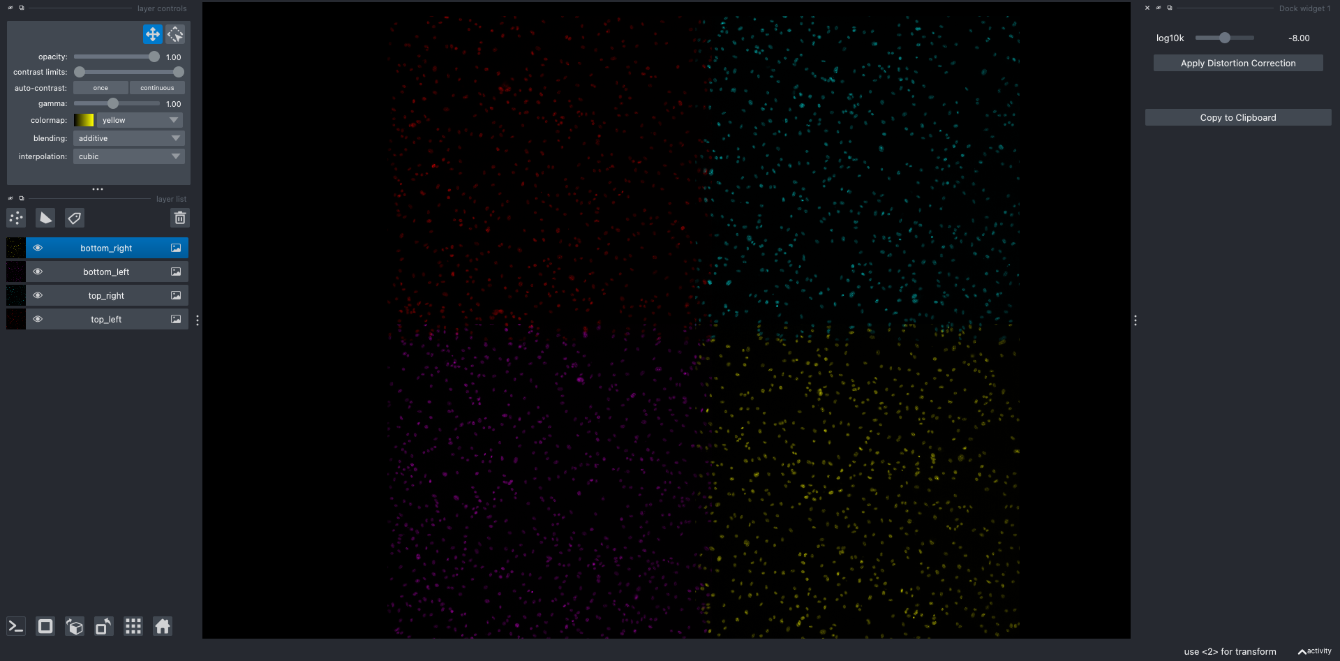
As you can see, the initial alignment of the images may not be perfect, so proceed to step 3.
Interactively Align the Images: In the left panel under the
layer listsection, select each image one by one. We recommend using the top-left image as your reference point, though you can choose any image as the anchor. Focus your alignment efforts on the central region of the images, where barrel distortion is typically less pronounced. Once an image is selected, click the transform button located in thelayer controlssection at the top of the left panel. This will allow you to move and align each image individually.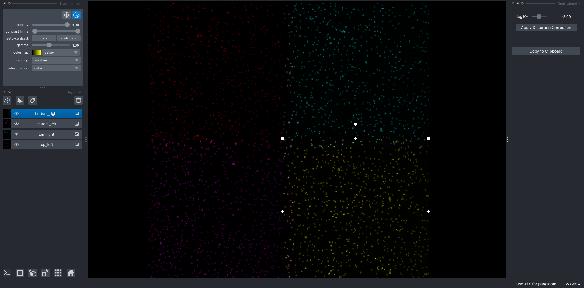
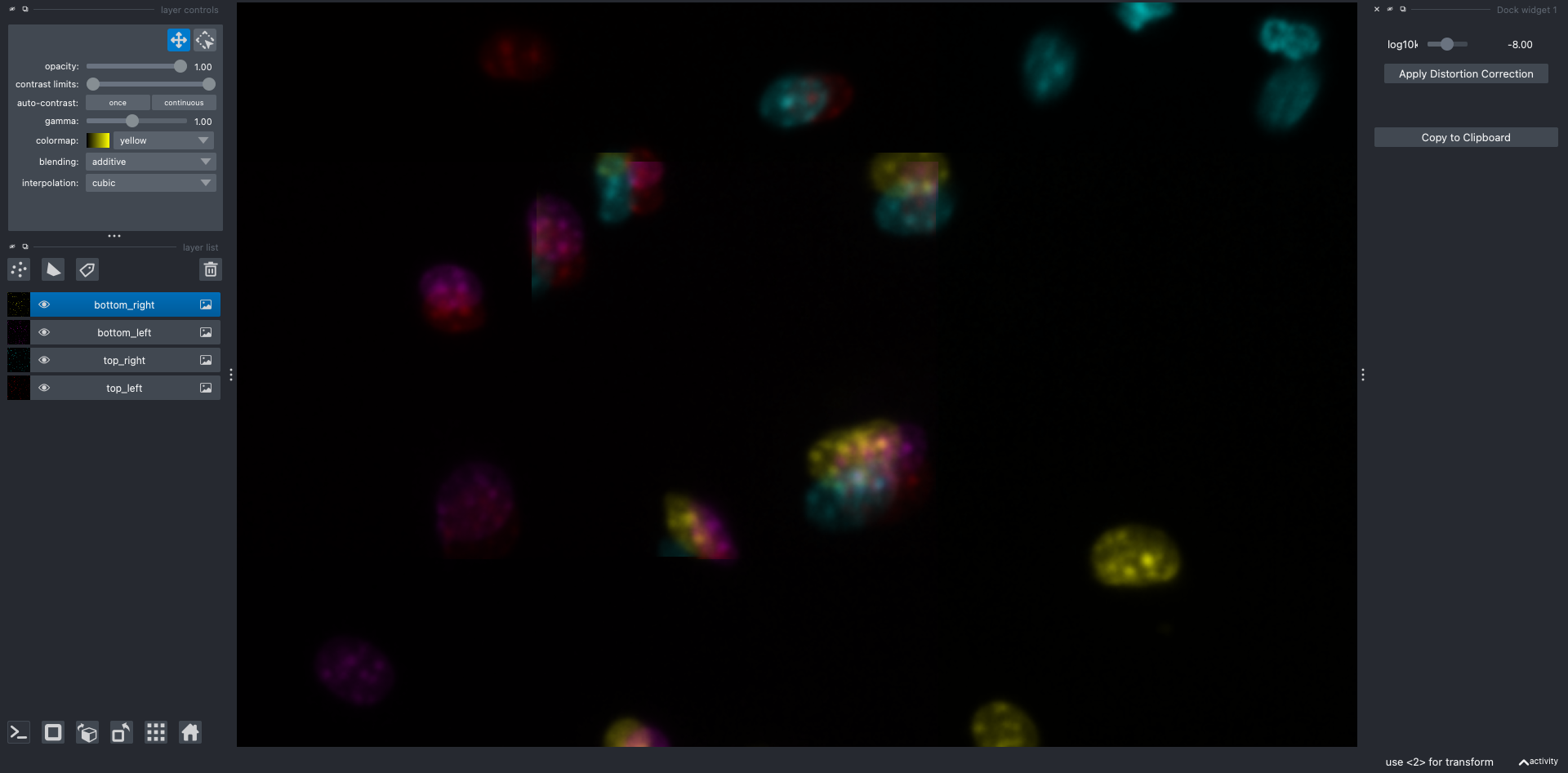
Interactively Adjust ( K ): Use the “Apply Distortion Correction” slider within the Napari viewer to adjust ( \log_{10}K ). As you move the slider, observe the changes in the image to achieve optimal correction where lines appear straight. Pay particular attention to the image intersections, while also verifying the correction in other corners.
Before Correction
After Correction
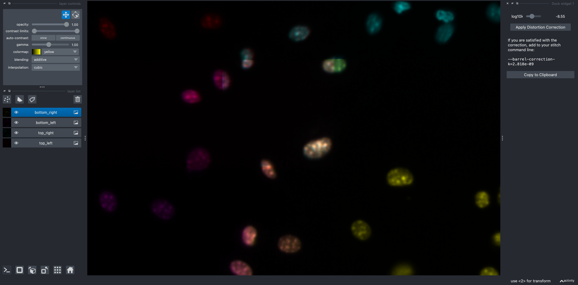
Note that you may need to re-align the images after applying the correction, repeating the process until you are satisfied with the result.
Record the Command: Once you’ve achieved satisfactory correction, the viewer will generate a command with the estimated ( K ) value. Copy this command to your clipboard. It will look like this:
--barrel-correction-k=<estimated_K_value>Integrate with ``stitch``: Incorporate the estimated ( K ) value into the
stitchcommand of thescallopspackage. This ensures that the barrel distortion correction is applied during the stitching process, resulting in a distortion-free and accurately aligned final composite image.scallops stitch --barrel-correction-k=<estimated_K_value> ...
By following these steps, you can effectively determine and apply the distortion coefficient ( K ) to enhance the precision of your image processing tasks. This integration of interactive visualization with automated correction highlights the robust capabilities of the scallops package in managing complex imaging workflows.